
Project ![]()
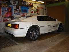
Turning an Esprit Sport 350 into a Sport 500
By Rob
C
Introduction
My back ground, I started working on cars seriously in the early 70’s with a family to support, I was working 18 hour days.
My main theme the Mini in all shapes and forms many modified. Today the 45th one, sits heavily modified lurks in my garage waiting …I’ve owned and restored so many cars I’ve lost track… But Lotus is my real passion and has been since watching early F1.... My first one an Elite, I built into a 275bhp monster in 1990.
The Project
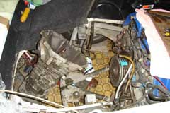
It started with the planning stage early in 2006 with sourcing all the major parts such as Hybrid Turbo's.. Forged Piston's.. Twin Inter-Coolers.. large Radiators.. plus and some what expensive small parts to boot…. Am I mad yes I guess I am.. after the events of the start of 2004 with the mishap, believe me this is kids stuff.So the Job started in Ernest.. Cover off the car and some shots taken before the car becomes a box of parts…
Tail Gate Removal
If like me you do not have the roof height to have the Tail Gate held vertical.. you have to remove it….
First off disconnect the Gas Struts… from the tail gate. .. the metal clips can be levered off care fully.. then the ball joints will pull off… Supporting the tail gate high.. disconnect the Aerial.So with the tail gate open at about the horizontal I attached it via ropes to the roof from the rear…then lining the mounting Hinges with masking tape to aid re-alignment when refitting…. I suspended the front at each corner while I removed those hinge bolts.. then when ready with a pal.. the tailgate was removed and stored vertical on the side of the garage wall.. all covered up.
Next the rear Diffuser was removed and repainted as my unit was modified and now turned into a wing with added aluminum its mounted as normal on by 2 x 10mm bolts from inside via a hole seen from below…Next Job the main Silencer..
Which My car does not use normally, for the road ..(giving an extra 10-20 bhp).. 4 x 13mm bolts on the Pipe Clamps. plus 2x 17mm Nuts and washers above the box itself.. this can be removed with the car on the floor…. I lower the box onto my chest then roll it on the floor.My Track Silencer … was a stock unit I modified with Twin 75mm Twin Pipes like the factory spec US item.. I built mine in mid 2002, the inside was also modified with about 100mm of the honey comb pipe wrapped with Stainless steel…noise level is 98DB but now it has a very efficient.. gas flow….the normal tail piped were removed and I capped the ends.. (I plan to remove half of the redundant metal work later)
Note removing the Silencer from a normal V8 will raise the rear suspension by about 15mm…. there is a 15mm Shim plate on the bottom of the Shock absorber that can be removed …you will then need a thin buttress plate to align the springs after…Not lowering the rear of the car will upset the balance…making the car over steer.. I did the test work on my 97 V8 in 99. ( proved on the race track)Next the Boot Floor what a pain the self capture nuts either turn or shear off…I plan to modify this later on…I had to grind most of the rusty mess off from below.
Gearbox Removal
First drain the special Oil.
Drive out the two Grover spiral pins in the Drive shafts.. be aware to make sure there exit is clear as they come out. .. My drift I made up is 5mm x 50mm welded to a l50mm long Bolt.. so you can get a clean shot with the hammer…to drive the Pin out.Next the Gear linkages… can be disconnected.. easy job.( I oiled the ball joints at the same time.
The Cats.. have 3 tab washers and are held in place with 13mm nuts x 3.
I labeled the Lambda sensor plugs as I disconnected them with tie wraps.
The Gear box Mounts are also an easy job …Bell Housing Area
At this time…Lifting the end of the gearbox up (ready for removal) slightly….. and supporting the rear of Engine by placing Wood blocks aprox 60mm under the Chassis Rails at the Bell Housing End .
Next remove the Bell Housing bolts…all but one top one…and remove the clutch drive arm plate with the slave cylinder…. The Clutch Arm has to be pulled out of the linkage as its actually held in place in the clutch Release Bearing which on our V8 Engines is actually attached to the Clutch plate its self.
Don't forget like I did to remove the 2 Earth cable on the gearbox.Drive Shafts Removal…
No 1…raise the rear of the car off the ground.. make safe.. use Axle Stands at the jacking pints.. by lifting under the rear Roll Hoop.. I built a special fitting for my trolley jack.
Remove the Upper Inboard suspension arm Bolts/washers at each side…one at a time.. Now the wheel can be pulled out wards to free the Drive Shaft.. from the gearbox.. Refit the removed suspension bolt/washers back into the mountings loose. Cover the CV Joints…and the Gearbox apertures holes…to keep dirt out.Rear Cross member raising the car under the Roll Hoop will take the tension out of the chassis… will aid removal of the 4 bolts…
Gear Box Out
Supporting the Engine and the Gearbox’s weight separately, next pull up the clutch Arm from its sprung fitting about 35mm. then you remove the last Bolt in the bell housing and slide the unit rear wards then lifted it up and out and dropped it down behind the back of the chassis onto the floor..Engine Removal
Mostly as per the work shop manual…disconnect the wastgate rubber pipes, the chassis Earth…Alternator wires… Crank Sensor….Oil warning light switch wire which up above and behind the Oil filter…
Remove the side covers in the rear engine bay… and then unplug all the Engine wiring harness out of the RH compartment.. note the Crank Sensor cable at the rear there.. ECM Plug and two other flat Plugs.. all straight forward stuff.
Unbolt the Aircon pipe mounting Bolt 10mm..under the front of the Engine.. as the plan leave the pump connected…but laying in chassis.Two not so nice jobs..
Power Steering Pipes…. First just loosen the 3x 10mm Bolts holding the Pump Drive Pulley On …then Remove Drive Belt…. which is real easy.. using a 1/2" ratchet in the Spring Loaded Unit turning Anti Clockwise to release the Belt …. Now the drive pulley can be removed……One rubber hose feed pipe easy…Seal this pipe or you will loose all your fluid…I used a bit of 15mm copper plumbing pipe.. end crushed and turned over.
2nd pressure metal pipe.. you need a Mirror & very short open ended spanner 150mm long 5/8AF or 16mm… note on removal the rubber "O" ring on the end of the pipe... this pipe needs to also sealed clean.. I pushed a piece of rubber pipe over the end.. and left vertical sealed.I have now found out there is another way to deal with the Power Steering Pump.. that is after you have removed the Drive Belt and the Drive Pulley as above… there are 3 x 13mm bolts holding the Steering Pump onto the Engine…remove and suspend the Pump safely will save having to drain the Fluid and making a mess doing so.
Oil Cooler Pipes…Two 28mm Flanged Pipes. They are very tight…I had to made a special tool from a Socket… I used a 5/8W socket I had.
Attach Tool to Outer Pipe & fit Jubilee clip onto it to hold tight and to stop to trying to spread open.. Undo and remove pipe whilst holding with a spanner on the coupler flange… and then remove the coupler itself….to gain access and Remove the 2nd Inner Pipe… Seal all 4 open Oil ways to prevent dirt entering...!!!
Note would be happy to advise on this Job.. its a Pigs EarAuxiliary minor Pipe work …. No problems there except the fuel line that is pressurized… it has a valve under a screw cap.. Be Careful and drain petrol into a container…
Water Pipes
Next a simple job…but when draining the Anti freeze from the header tank etc….I suggest refit and seal the Alloy pipe across the back of the engine.. "It feeds the auxiliary Electric water pump.. keeping the water flowing in a situation when the Engine gets very hot."
There is no need to drain any water from the Radiator and Pipe work…the Engine input & output pipes are way above the Radiator level.
The Engine can be drained later.Engine Mounts …. 19mm ring spanner and 10mm Allen Key…easy job…make sure you do not displace or loose the packing washers at each side.
Have you missed any thing ….. have a good look around !!!
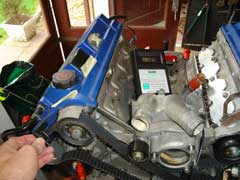
Lifting Engine Out
With the car back on its wheels… I made up my own lifting brackets… front mounting holes are 35mm centered and rear engine mounting holes are 45mm centered…with 8mm holes drilled… get bolts long enough to fit well into the casting.
Now your ready to start the lift attach a good Block and tackle.. lift the engine slowly some 150 to 200mm you can then remove the 3x17mm bolts holding the Aircon Pump on.. (note the 3 different lengths Longest top front--shortest at the bottom) lay pump on chassis.
Gently raise engine above the body work…Roll car forward….Lower Engine down…
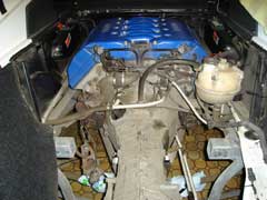
In my case when lifting the Engine Out as per the mountings at front left and rear right the Engine was tipping to the left as seen from the rear of the car….Actually putting the Engine into the Engine Stand was a pain for the same reason…I have now devised a Rope Sling that fits across the rear of the engine to keep the Engine square and level when liftingFront Inter Cooler Radiators remove the front centre under tray work 10mm bolts the Inner shroud intake is held in place with two Phillips headed bolts.. a pain to remove.. I replaced with studs and will fit nuts.
My car uses two auto transmission Cooler radiators mounted top and bottom inside the nose of the car from my good pal Johan in USA
Two 25mm holes with grommets in the front under tray near the drain hole feed the 15mm copper in and out…. All copper work has sleeving to stop any chaffing.Chassis Inter Cooler Water Feed Work
I used Copper plumbing fittings which are mounted on galvanized plates under the power steering mounting bolts along under the chassis the pipe work starts briefly at 15mm at the front of the car and then runs along in 22mm Copper Pipe to the rear of the Car before stepping back down to 15mm.. total length just over a meter.
… I used plastic plumbing fitting which are cable tie wrapped on…for security .. Care taken on the design at the Seat Belt Earth points…15mm Rubber Water Pipe connects all the Cooper work up.
At the Rear n/s up behind bulkhead to the Pump mounted on the chassis and then up and behind the heat shield in the n/s of the engine bay to the new cooler header tank and then on to the two inter Coolers before proceeding via the o/s inner panel and back down the rear of the bulkhead to join the copper work mounted on the under side of the chassis.. A sensor in the new header tank same as original Engine header tank gives warning of low water level.. will be wired in parallel to make use of the same water warning light…on the dash panel.
At the Front again 15mm water pipe feeds forward to the two front mounted cooling radiators which are mounted in the nose of the car in front of the normal Radiators these are connected in parallel being fed via 2 x 2 Y sections (made up in copper 15mm to two 10mm outlets/inlets)Electrical Modification's
As I had already modified my car's cigar lighter fuse A7 to have a permanent live... that positive feed now coming from the left hand electric window supply core on fuse A12…398N see sheet 16
The trickle charger can now be connected very quickly.The redundant Ign Switched live core 204W now feeds the extra equipment, via inline fuses.
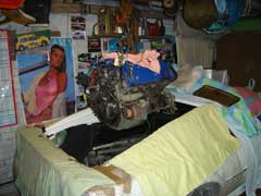
The Engine
Special tools made
One off Oil Cooler Pipe Flange Nut…Release Tool
4 Cam shaft Tolerance pins…(4 x 4.2mm ) plus the crank locking (peg) tool that fits in place of the Crank Sensor (Ign timing etc) mounting hole for Cam timing.
Cam Shaft Sprocket release Tool
Cam Shaft holding spanner 23 to 24mm
Cam Tensioner Tool
Inlet Manifold to Plenum alignment Gig Plate.
Crankshaft Main Bearing Cap removal ToolGeneral Info
One needs to be aware how the Cylinder No's they are laid out..
Right bank ….1234 back and Left bank is 5678 back… seen from the Flywheel end.
The Ign leads across from the opposite Ign Coil in the Vee of the Engine under the plenum chamber…
When Disconnecting all the Engine harness Connection Plugs add markings or labels … it’s a Huge loom.. take care.Begin…Strip Down…
Assuming the Engine is fitted to an Engine Stand…and all the ancillary parts are removed like Plenum/Starter/Alternator….the Exhaust does not need to be removed…..but I did remove mine…the 13mm/1/2 AF Nuts can be hard to remove due to Rusting away…. The 6mm heat shield nuts rust away badly (I welded short 8mm bolt shanks to them and managed to undo them…and the shields them selves also crack… both mine needed repairs.
Again assuming the two turbot’s and Water and Oil pipe work has been removed.The Plenum chamber comes off easy…
The Exhaust Manifold Heat Shields.. use 6mm nuts…which rust away…needed some thought… The Exhaust Manifold Nuts I found on my Engine were 13mm on one side and 1/2AF the other side… some also needing TLC ..via my Mig welder.
The Turbo mounting Nuts 12mm are on 10mm studs are very Special Kayloc nuts and very thin…huge care needed.. as they are very expensive.. best advise use a Oxy acetylene rig and get them real hot first.
I did not realize they were so special…I damaged 5…beware they are around £12 each from Lotus.. or about £60 a set from E bay..
Cheaper from SJ’s but these are not the actual correct ones, they look the same.
So you should have now removed things like the Starter Motor.. Alternator.. Cam Covers.. Manifolds.. inlet/ex.. water/oil pipes…Harness wiring ..Aux Drive belt…. Always use clean covers over the open Engine parts.Cam Belt Removal
To Fit the Cam Locking Pins (4.2mm) into the 4 Cams with the Crank locking tool in place ..via the Front Pulley… you will have to rotate the Engine Clockwise as seen from the front.(Cam Belt end) … best use the Flywheel to rotate…(Note…you will hear the Cam Gear clicking clunking its normal ) the locking tools will only fit in the one position so rotate the crank until they will all line up.. its at 10 degrees BTDC with No2 Firing.Next using the Cam Tension tool.. release the Belt tension and remove both Cam Belts RH 1st.…mark the belt rotation and side etc.
Gently undo the Head Bolts as per the Lotus manual…starting at the outside and working inwards to the middle of each Head…gently undoing each bolt a small amount… then moving on the next one in sequence.Head being taken Off
Before lifting off the Heads be aware some of the valves will be open…so the head cannot be laid down against the Head Face… Damage will occur… with my Heads.. I laid strips of L shaped wood down each side edge of head face.. and the head face as a unit was covered completely with plwood to keep dust and dirt out...Sump
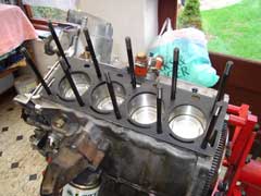
Sump Removal.. 24 bolts.. only issue is 2 of them are 6mm Allen bolts behind the Flywheel…. No gasket is used just RTF glue.Remove Piston’s …
again as per the manual… release each Big End bolt gently, and remove the cap with bearing shell…then push the Piston out of the Liner.. taking care not knock the bearing journal with end of the Conrod… refit the cap…note which Piston it is…and how it was fitted in the bore.. mine
were marked on the side of the big end casting of the con-rod…these marking are visible on the con-rod’s when looking at the crank from the sump.
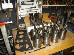
Store the piston’s/Conrod in clean carrier bags like I did and store safely in cardboard boxes.. till later.Remove the Liners…
A tool is required.. which sits on the bottom of liner with a recess to keep it central… mine has the same fitting at the top of the liner with both attached with a long threaded bar.. about 12mm in diameter.. that extended above the liner to form a slide hammer.. which in turn removed each liner…which must be numbered according to its block position… mine were already marked on the side of each one..
The next job is to clean the block and the liners of all the old glue… and then De-glaze each liner.. in a cross hatch action.Re-building the Engine….
Assuming all the parts are clean and grease free…care must be taken not to mark or damage any alloy face when cleaning.
The Liners
must be fitted with a Cylinder Head torque’d down within 4 hours for the Liner Glue to cure correctly.
I choose to fit all 8 liners in one go…this is how I did it…!!!
I had already completed the Piston Ring gap’s adjustment as per the JE Forged piston guide … and prepared Liners, by Deglazing the Bores… I then removed the fully floating old Lotus Piston’s from the Con-Rods which is easy… I had washed the new Piston’s as instructed … I then fitted one Gudgeon Pin locking ring into each Piston first…..then oiled the new Gudgeon pin and fitted it into the numbered Piston and Conrod… fitting the 2nd locking ring is difficult but best done I found with two small terminal screwdrivers to spring in place in the end of the gudgeon pins locating ring in the Piston. I did this job on a soft protective surface.
Now taking each numbered Piston (Conrod) in turn I fitted the prepared rings for it and then using my piston ring compressor fitted the piston/con-rod into the correct Liner… until all 8 are made up.The Big Task…Building the Short Block…
This major preparation task must be made with all tools.. parts.. cleaning agents etc.. the Liner Glue Hyloma 3400 laid out carefully…. before attempting this next stage.…Noting where each Piston/Con-Rod assembly is to be fitted with the Numbered Con-Rod’s showing face up to you when fitted to the Crankshaft.
With the faces of Liner and Block immaculately clean…spread the Glue around the Block face and the liner face.. with a bead about 10mm down the Liner mating face… Having removed each Big End cap in turn…taking care with the end of the Con-Rod… not to hit the bearing journal face…Start with No1 and slide a Liner / Piston Assembly into the block and attach the bearing cap back on the Con-Rod finger tight…do the same with No 2.3.4 Next strap a tight piece of heavy string across the head face diagonally …with small blocks of wood across each pair of liners to keep them held in place.
Now complete the other side of the Block starting with No 5...6.7.8.When all 8 liner assemblies are fitted.. At this point the Crank shaft should be at 10BTDC with the Crank locking tool in place.
Fit the sump with a couple of bolts finger tight… Next Screw in tight the ARP head Studs, then fit the Head gaskets…noting the dowel positions. Fit a Cylinder Head… Oil the head stud threads (engine oil)…(Take care not to drop any washer/nut into oil ways)…fit the washers/nuts finger tight ….complete the other Head the same…Care should be taken to ensure the Stud large washes do not foul the camshafts
Torque down the Cylinder Heads Nuts to 85ft/lb. In stages, gently, as per the workshop manual sequence starting in the centre and work your way out wards.
Next stage re-fit the Old Cam Belts..
Re-fitting the old cam belts is required to replace the Crank Shaft Big Bearings…with ACL race spec items as per the manual..
Note…the 4 Cam Shaft Locking 18mm Nuts are Nipped up very gently. (beware there are Locking Pins in the Camshafts, at this time.)
Once the camshafts bolts are nipped up, remove the locking pins, before torque-ing the bolts up correctly( Having already used my Main Cap removing tool, very similar to the factory tool to inspect the No 4 main bearing as a precaution….in my case I found the Shell bearings very good.. and also the Thrust Washers 100%.
So Rotate the engine clockwise from the belt end.. to enable replacing the shell bearings.. two piston’s at a time. Using Engine Oil lubricate the bearing faces.. Do not oil between the Con Rod face and the shell bearing.
See Big End Bearing Data fitting.
|
|