Keyless entry for Esprit's
with the factory Megamoss alarm!
This procedure should take around 2-4 hours to do for someone who is as electrically challenged as I am. An expert will finish faster. (All images are quite large and can be saved locally for viewing full size.)
When complete you will have a keyless entry unit that is wired for the following functions:
1. Alarm the car
2. Disarm and unlock
3. Windows up (requires one-touch window kits)
4. Windows down (requires one-touch window kits)
5. Lock without the alarmThis leaves two more functions for trunk release or whatever you wish to add in the future. In addition, all locking, unlocking and alarm functions are still enabled through the key in the driver's side door.
Due to the relay functionality a small amount of current will be drawn (300-600 mA) when the car is either unlocked (with key or remote) or alarmed with the remote. To avoid this miniscule drain when unattended for long periods you can lock your car without the alarm or enable the alarm with the key.Another option is to install a capacitor that will turn the constant output when unlocked into a pulse. I didn't do it since there was already a lot of wiring to be done and I don't have a problem leaving my car door locked. :) Instructions can be found on The 12 Volt website, which I must credit for my new understanding of relays and switch building. A constant to momentary output switch is shown here, though you'll have to convert it to a negative switch instead of a positive switch.
Quick Synopsis
What you will need:
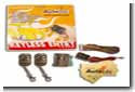
1. KL700 Keyless Entry Unit from Autoloc. This can be purchased online fairly easily. (Milito Auto Accessories has the best price as of this writing)
2. (4) 30A SPDT relays. You can buy these at Milito also, or get authentic Bosch relays at Parts Express for less.
3. Wire cutters
4. Wire strippers
5. 12 and 16-18 ga. wire
6. (16) 1/4 in. insulated female blade connectors (for connecting to the relays)
7. Soldering iron and solder
8. Electrical tape
9. 13mm socket
10. Zip ties
11. 30A fuseSteps:
1. Disconnect the battery!
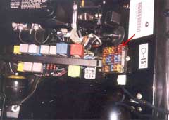
2. Replace the CDL 10A fuse with a 30A fuse.
3. Remove driver's seat for easy access - trust me.
4. Tap into the driver's side wiring.
5. Tap into the positive and negative battery feed.
6. Tie up all wiring and the Keyless unit under the dash.
7. Replace the seat and reconnect the battery.
Caveat
I've noticed that on a few occasions the passenger door does not respond to lock and unlock commands like it should. This has only happened a couple of times, but it is worrisome. I believe it has to do with the way I have the unit wired that one of the electrical paths may be hogging the power when it's needed to trigger the central door locking (CDL) mechanism.I also don't like that the 10A CDL fuse needed to be replaced with a 30A fuse. It shouldn't need that. I assume that a couple of strategically placed diodes will solve the problem, but I didn't know what size and where to put them. If anyone can figure out why these problems are occurring I would sure appreciate it - and credit you of course.
Theory behind the installation
Both the Central Door Locking (CDL) unit and the Alarm wiring are a pain to reach, and installation is impractical tying into these units directly. It dawned on me that the alarm system and CDL functionality is all controlled from a much easier source to reach - the door. With that in mind I set out with a multimeter and a screwdriver and got it all sorted out.After taking the door apart and testing every connection against the Driver's Door Harness Connector (DDHC) I was confident that it could be done. In order to trigger the behavior I wanted I just needed to apply a ground wire to one of the DDHC wires in a pulse, except for the alarm which requires a constant ground. Truthfully, locking and unlocking require a contant also, but the very act of triggering the event turns the pulse into a contant anyway. Here are the results of my testing:
Status Wires in Continuity Trigger Pulse or Constant Unlocked Orange & Orange-Red Pulse Locked Orange & Orange-Blue Pulse Alarmed Orange & Orange-Blue & Orange-Yellow Constant Finding a keyless unit was simple for locking and unlocking. I just needed one that would output a negative trigger. I chose the Autoloc KL700 because it has enough triggers for me (7) and it includes code rolling technology (unlike the KL800) to make it harder for thieves to capture the code used to communicate with the unit.
Enabling the alarm was a lot more difficult to figure out. The Orange wire is obviously the contant negative wire, so I just needed to find a way to get it to link to the Orange-Yellow wire for the alarm. That's where the relays came in and solved the problem by creating an isolated dual input and dual output switch.
Detailed Instructions
Disconnect the battery negative cable before you begin. This is important not only because you're working with the wiring, but also because you will be working close to the airbag circuitry. You definitely don't want to tamper with that! It can take up to 10 minutes for the airbag circuitry to discharge to the point it is safe.Replace the CDL 10A fuse with a 30A fuse. It's the top left one when looking at it from the front. In the Service Notes it's conveniently numbered #1.
Then remove the driver's seat. There are 4 bolts under the car with 13mm hex nuts I believe. Just be very careful of your leather when you remove the seat.
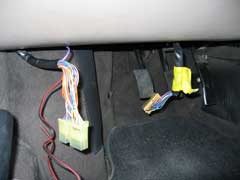
Disconnect the driver's door harness connector (DDHC) located close to the door under the dash. Also disconnect the steering column harness connector (SCHC) which looks just like the DDHC. Do NOT disconnect the airbag connector by mistake.
Splicing:
1. Splice into the brown-red wire on the SCHC. This is an unfused battery positive.
2. Splice into the black wire on the SCHC. This is an unfused battery negative (ground).
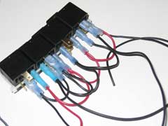
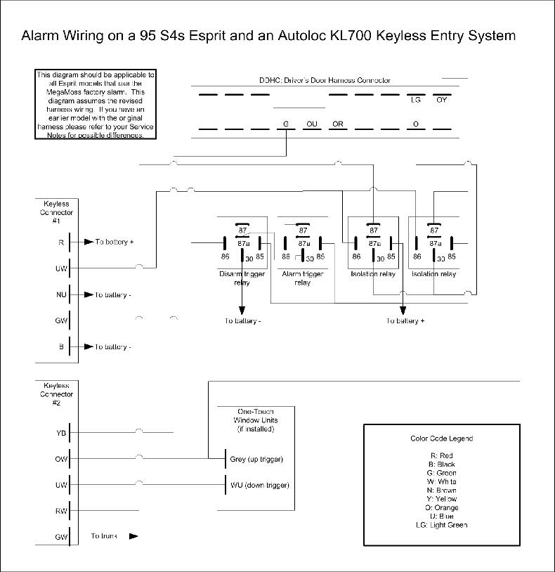
3. Build the array of relays and wire everything up according to the diagram below. (There are too many links to explain it briefly here. The diagram is a lot easier.)
4. If you are not installing one-touch windows you can safely ignore those connections.
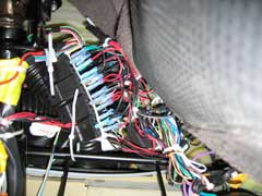
5. Solder the red wire from the keyless unit to the battery positive wire.
6. Solder the black wire from the keyless unit to the battery negative wire.Picture shown below with splicing in progress. The installation of one-touch windows is also shown, but you can ignore the gray boxes on the left unless you are installing them also.
Here is the wiring diagram. You may have to save it locally to zoom it into legibility. It prints well too:
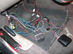
Reconnect both harness connectors. At this point you should be able to reconnect the battery and test everything. If it all works then take zip ties and tidy up the wiring. If you look under the dash close to the door you will see a lot of space available for you to tuck everything up there. Use zip ties to hold everything up there, but be careful not to impede the movement of the front bonnet release lever.
If you have any comments, feel free to e-mail us at admin@lotusespritworld.com
![]()
|
|