
Wiper Motor & Linkage Repair

How much play is there in your Esprit wiper arm? In the parked position move it up and down across the screen. If the linkage is in perfect condition there should be no more than 2cm of movement at the end of the blade and it should feel stiff and springy. If there is more movement, first try to establish if there is movement between the wiper arm and the spin- dle. If there is, then try tightening the nut on the end of the wiper arm, or replace the arm if worn. If this is not the problem then the movement is caused by a worn linkage under the dash, most likely where the spindle attaches to the linkage.
If it is a problem with the linkage you can correct it by purchasing a new linkage which comes complete with the motor and costs in the region of £350. You can then take it to your usual service agent for fit- ting, but this will cost you about 6 hours labour. However, the linkage is repairable so why not do it your- self for nothing? It's not as daunting as you might think, but it does take a bit of time. Here's how to remove the linkage and repair it.
The following applies to post 1998 cars, although earlier cars will be very similar. Access under the dash is very limited so part of the dash will need to be removed.
As always, first disconnect the battery. Now create access to get under the dash.
Remove the steering wheel by prising off the centre cover, discon- nect the horn push wires and then releasing the steering wheel by removing the four Allen bolts. If you have an air bag, then follow the instructions in the manual.
Remove both seats, four nuts each under the car.
Now, if you lay on the floor and look under the dash you can see both the wiper motor and the link- ing bar. To improve access to both you need to remove the knee bol- sters and the heater trunking.
LH Knee bolster and heater trunk- ing: The LH bolster is held by a bolt inside the centre console, a nut on a fixed stud behind the face vent, a nut and bolt behind the A pillar trim and two screws under the glove box lid. Remove the glove box lid then put some padding (eg wrapping with masking tape) on the ends of the hinge springs so that they don’t mark the dash. Remove the two black screws which fix the bolster to the steel dash brace. Remove the radio and its mounting plate (see instructions that came with your radio). You can now see and remove the bolt that screws through the centre console into the bolster. Ease out the face vent and release from the trunking. You can now see the nut that needs to be loosened on the stud, but not fully removed and one end of the nut and bolt combi- nation. Remove the door seal and carefully ease the A pillar trim away from the body. If the A pillar trim at the top is fitted behind the cant rail then both this and the header rail must be removed. The header rail comes off first, held on by two screws behind each sun visor. The cant rail is held by two screws from the outside of the door aperture.
The A pillar trim is held by three clips close to the windscreen. Lever the trim towards the centre of the car to release. If it doesn't come off without a lot of force you may be unlucky and find that when the wind- screen was fitted the bonding agent was squeezed onto the trim and it is now stuck to the windscreen. Before taking a Stanley knife to the gap between the windscreen and trim (and possibly ruining the trim) see if the bottom of the trim can be eased out enough to get access to the nut and bolt. I was lucky enough to do it this way. Remove the nut and bolt.
Carefully ease the bolster towards you lifting slightly as you do and release the alarm module from the back of the glove box (slides off) and the wires to the footwell lamp.
Now from under the dash release the windscreen vent hose at the heater. Next release the footwell hose from the heater, cut the cable tie and remove the hose. The wind- screen vent hose can now be released from the vent and removed and the face vent hose released from the heater and removed.
Unfortunately you will now need to remove the windscreen vent itself to be able to move the wiper motor. This was fitted at the factory before the windscreen was fitted. You will need a small angled screwdriver, or a driver bit firmly fixed into a small spanner. Once the two screws are removed the vent can be eased out from under the dash.
RH Knee Bolster and heater trunking: The RH bolster is held by two nuts on fixed studs at either end, two 10mm nuts at the top and a 8mm nut behind the face vent. Remove the instrument binnacle cover by releasing the two Torx screws above the rev counter and speedometer. Slightly lift the cover and pull towards you. Remove the instrument panel by releasing the two bolts holding it to the steel dashbrace and the screw at either side. Lift the panel out releasing the two wiring connectors as you do. Ease out the face vent and release from the trunking. At the front of the venthole is a 8mm nut, remove this nut and its washers. From beneath the dash loosen the nuts on the studs at each end of the bolster, again don’t remove them. From above remove the two 10mm nuts, the one near the centre of the car is accessed through a hole behind where the instrument panel was, the outer one from through the face vent hole. Carefully ease the bol- ster towards you lifting slightly as you do and release the wires to the footwell lamp. From under the dash release the windscreen vent hose at the heater. Now release the foot- well hose from the heater, cut the cable ties around the windscreen vent hose and the loom and remove the hose. The windscreen vent hose can now be released from the vent and removed and the face vent hose released from the heater and removed.
Removing the wiper motor and the wiper linkage: Remove the wiper and the pantograph arm, then from outside the car remove the two small bolts from the mounting plate.
Carefully remove the spindle nut and washers. The right hand end of the wiper assembly is now free. Remove the three nuts and washers from under the dash to release the wiper motor. A second person will be required to hold the bolts from the outside. Now working from both sides a bit at a time turn the whole wiper assembly over so that you can access the connecting side of the wiper motor. Disconnect the wiper linkage from the motor. This can be done by removing the nut on the motor spindle, although I chose to release the circlip at the end of the linkage arm so that the turning lever on the motor retained its original position. The linkage arm can now be removed from the driver's foot- well. If you need to remove the motor this can now be done from the passenger footwell after releas- ing the connector.
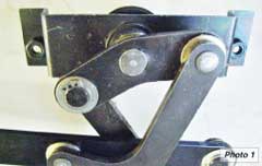
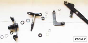
Repairing the worn spindle: As mentioned before, the most likely problem is a where the spindle attaches to the linkage. This is what the end of the linkage looks like. (Photo 1). The spindle, shown in the centre of this picture, is a square pin in a square hole. It is only peened over, so if it isn't a good fit in the first place there will be a small amount of play which will increase as the wiper is used and the spindle wears. A simple repair is to weld this spindle to the lever. Don't weld this in situ as the spindle has a rubber seal and the pivots have top-hat plastic bush- es. You will need to release three pivots to separate the spindle and mounting bracket from the linkage. Now remove the circlip at the end of the spindle and ease the mounting bracket away. It now looks like this. (Photo 2). Now you are free to weld the back of the spindle and when cool re-grease and put it all back together. Make sure the bushes, washers and circlips are reassem- bled correctly. Mine got a nice coat of paint as well, although I hope I'll never see it again.
Replacement is the reverse of removal as they say in the manuals. Here are a few extra hints: Once you have reconnected the linkage to the wiper motor and turned it over, push the spindle through the hole in the scuttle and lightly secure with the large spindle nut and washers. You can now manoeuvre the mounting plate in position and secure with the two small screws before finally tighten- ing the spindle nut. When the motor is secured, connect the battery and test! Disconnect the battery before continuing. Make sure you refit all the parts in the same order that you removed them otherwise you may find that you have restricted access to fit the next part
When it's all done wait for a rainy day and go for a drive.
Many thanks to Tony Butler for the welding on my spindle.
![]()
|
|