Bleeding Brakes
Delco Moraine ABS IIIA (MY90-MY96)
You'll need to bleed your braking system (remove air from the fluid) everytime you change your brake fluid or remove/change your calipers. The procedure below is for the Delco Moraine system, which started off in the Esprit SE and was superseded by the Kelsey-Hayes Antilock Brake System in the MY97 V8's. The Delco system is pressurised and is slightly different from standard systems. This page is to guide you through bleeding this pressurised system. The later system on MY97 Esprit onwards using a standard system and can be bled the normal way.
Bleeding the system removes air from the fluid. Air reduces the performance of the brake fluid and can give your brakes a spongy feeling and increase braking distances. It's important not to have air in your system. Following the procedure below to get the best out of your brakes.
Time to complete: 1-2hrs
You will need the following parts:
1 litre of Dot 4 Brake Fluid
You will need the following tools:
Jack and Axle Stands (or lift)
10 & 11mm Spanners
Bleeding Pipe
Jam Jar
Delco Moraine ABS IIIA
BRAKE BLEEDING PROCEDURE
If a Powermaster IIIA booster/master cylinder assembly, or a pump/accumulator assembly has been replaced, or if air has entered (or is suspected in) the brakelines, the entire brake system including all hydraulic units must be bled at each wheel. If only a hydraulic part of the booster/master cylinder or pump/ accumulator has been replaced, and air has not entered the brake lines. it may only be necessary to bleed at the booster/master cylinder bleed nipples.IMPORTANT: De-pressurise the accumulator. Always de-pressurise the accumulator before performing any service operations. When the system is pressurised, most of the fluid is stored in the accumulator, and the reservoir level is correspondingly low. Topping up the reservoir in this condition will result in overfilling. Although the fluid reservoir is not under pressure, if the brake pedal is operated when the reservoir cover is removed and the system is pressurised, returning brake fluid may spray from the reservoir.
Manual Bleeding
1. Ensure ignition is switched off. 2. De-pressurise the accumulator by FIRMLY applying and releasing the brake pedal up to 40 times.
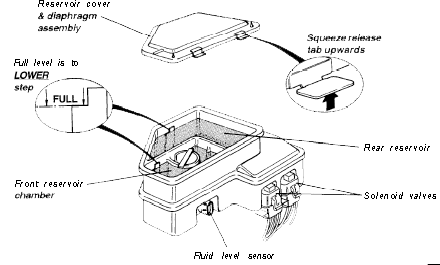
A noticeable change in brake pedal feel (to a hard pedal) will occur when the accumulator is completely discharged.3. Clean the reservoir cover and top of the reservoir before squeezing the release tabs and lifting off the cover and diaphragm assembly. 4. Fill or top up both front and rear compartments using only DOT 4 brake fluid from a sealed container until levels reach the full marks.
IMPORTANT - Use only DOT 4 brake fluid. Do not use DOT 5 silicone fluid, or any fluid which has been exposed to the atmosphere for more than a brief period, or any fluid suspected of being wet, dirty or contaminated.
Refit the reservoir cover and diaphragm assembly.5. If a replacement booster/master cylinder assembly has been fitted, or if there is difficulty when trying to bleed the front master cylinder sections,ensure all air is removed from the master cylinder body by opening the brake pipe tube nuts on the master cylinder (front two only) approximately two turns, or until fluid begins to bleed. Torque tighten the pipe nuts:
– Front pipe (LHF brake) M13: 24 - 26 Nm (18 - 19 Ibf.ft)
– Second pipe (RHF brake) M12: 22 - 24 Nm (16 - 18 Ibf.ft)6. Bleed right front wheel brake:
– Attach bleeder hose to caliper nipple and submerge opposite end in clean brake fluid.
– Open bleed nipple.
– Slowly depress brake pedal.
– Close bleed nipple.
– Release brake pedal.
– Check fluid level and top up as necessary.7. Repeat step 6 until the brake pedal feels firm at half travel and no air bubbles are observed in the bleeder hose. 8. Repeat steps 6 and 7 on the left hand front brake. 9. Turn the ignition on and allow the pump to run and pressurise the accumulator.
NOTE: Turn off the ignition if the pump runs for longer than 60 seconds, and refer to ‘Pump Runs Continuously’ (see later).
10. Bleed right hand rear caliper:
– Attach bleeder hose to caliper nipple and submerge opposite end in clean brake fluid.
– Open bleed nipple.
– With ignition on, lightly depress the brake pedal until fluid begins to flow from the hose.
– The harder the pedal is pressed, the more fluid will flow. Do not fully depress the pedal.
– Note that the pump will run during this process. Allow fluid to flow for about 15 seconds.
– Close bleed nipple, then release brake pedal.
– Repeat as necessary until no air bubbles are seen at the bleeder hose.11. Check fluid level in the reservoir rear chamber. To avoid de-pressurising the accumulator at this interim stage, top up the reservoir rear chamber to a level 25 mm below the full mark.
IMPORTANT: Final fluid level must be checked after de-pressurising unit at step 14.12. Repeat steps 10 and 11 for the left hand rear caliper. 13. Bleed master cylinder isolation valves:
– Attach a bleeder hose to the bleed nipple on the inboard side of the master cylinder, and submerge
– opposite end in clean brake fluid.
– With ignition on, apply light force to the brake pedal and slowly open the bleeder valve to allow
– brake fluid to flow until no air is seen in the fluid.
– Close the bleed nipple when fluid begins to flow without air bubbles.
– Repeat procedure on the outboard side nipple.
(or use the ‘Tech 1’ bleeding sequence)14. Bleed accumulator:
Turn off ignition, de-pressurise the accumulator by FIRMLY applying and releasing the brake pedal up to 40 times. A noticeable change in brake pedal feel (to a hard pedal) will occur when the accumulator is completely discharged.
Wait two minutes for air to clear from-the brake fluid in the reservoir.
Remove the reservoir cover and check the level in both front and rear sections of the reservoir.
If necessary, top up to the correct level - see start of this section. Refit reservoir cover.
Turn on the ignition and allow the pump motor to run.
NOTE: Turn off the ignition if the pump motor runs for more than 60 seconds. Refer to ‘Pump Motor Runs Continuously’ in this section.15. Bleed booster section of the booster/master cylinder assembly:
Depress the brake pedal with moderate pressure and turn on the ignition without starting the engine for 3 seconds.
Repeat this off/on procedure 10 times to cycle the solenoids.
(part of ‘Tech 1’ bleed sequence)16. Assess brake pedal ‘feel’:
Apply brake pedal and note pedal feel and travel.
If pedal feels firm and smooth without excessive travel, system is properly bled.
If pedal feels soft or spongey or travel is excessive, refer to ‘Excessive Pedal Travel’ in this section.
If a ‘bump’ is noted upon initial pedal application, or application does not feel smooth and uniform, refer to ‘Non-Uniform Pedal Feel’ in this section.17. Road test vehicle and note pedal travel and feel. If any symptoms described above in step 16 appear, refer to the appropriate section below. Excessive Pedal Travel
Excessive brake pedal travel exists if, when driving the vehicle, braking action does not start until after the first 35 mm (1.4 in) of pedal travel. If after carrying out the brake bleeding procedure above, excessive travel is evident, proceed as follows:
1. Re-bleed front brakes (rear brake circuit may be omitted) as described above in steps 6, 7 & 8 of ‘Manual Bleeding’, and check brake fluid levels. 2. Re-assess pedal feel as in step 16 of ‘Manual Bleeding’ above. If excessive travel is still evident, first check fluid level, then check for leakage throughout the brake system. Non-Uniform Pedal Feel
Bleed the system using the ‘Tech 1’ bleeding procedure.Pump Runs Continuously
IMPORTANT: This procedure is to be used if the pump runs for more than 60 seconds.
1. With the ignition off, de-pressurise the accumulator by FIRMLY applying and releasing the brake pedal up to 40 times. A noticeable change in brake pedal feel (to a hard pedal) will occur when the accumulator is completely discharged.
NOTE: In the following steps, use a suitable container and/or shop towels to catch the brake fluid and prevent it from contacting any painted surfaces.2. Loosen but do not remove the two tube nuts from the master cylinder front chamber (for the left and right hand front brakes). 3. Press the pedal to its fullest extent. Fluid should run slowly from around the tube nuts. 4. With the pedal depressed, tighten both the tube nuts. 5. Quickly release the pedal and re-apply using a jabbing (sharp and rapid) motion with full force. 6. Turn on the ignition and allow the motor to pressurise the accumulator. 7. Assess brake pedal feel, and road test-as in steps 16 & 17 of ‘Manual Bleeding’.
IMPORTANT: If the pump still runs continuously, refer to ‘Hydraulic Diagnosis’‘TECH 1’ CHECKING PROCEDURES
Fault Codes
When the ABS controller detects a fault in the’ system, the following events occur;i) The ABS tell tale is lit:
ii) The anti-lock system is switched out;
iii) A fault code is stored in the Non Volatile Random Access Memory (NVRAM) i.e. memory which is retained when the power supply is interrupted, or the battery disconnected.Fault codes may be either Condition Latched, or Ignition Latched:
Condition Latched; With this type of fault, which is generally low or high voltage, the ABS tell tale will light, and the anti-lock system switch out, until such time as conditions return to normal, at which point the light will be extinguished, and the anti-lock be reinstated. The fault code will be stored only whilst the fault is present.Ignition Latched; This type of fault, of which are most categories, will cause the tell tale to be lit and the antilock to be inhibited until such time as the fault is no longer detected at the moment of a subsequent switching on of the ignition. At this point, the lamp will be extinguished, and the ABS restored, but the fault code will be retained in the memory for the next 20 drive cycles i.e. ignition switched on and a minimum road speed of 5 mph attained.
Access to the diagnostic codes is available only by using the ‘Tech 1’ tool connected to the DLC. The ‘Tech 1’ is a hand held electronic scanner tool with an LCD display panel which is able to display any stored trouble codes and sensor readings as well as allowing manual operation of actuators.
The facilities available include:
Clear fault codes
View fault codes/wheel speeds/valve activities
* Generate valve/motor activities
Read EEPROM contents
- Read ECU identificationlmportant Notes
- Whenever the Tech 1 tool is connected, the ABS tell tale is lit and the anti-lock function is inoperative. Never connect or disconnect the harness plug to/from the control unit with the ignition switched on. Before charging or quickcharging, disconnect the battery from the vehicle electrical system.
- Never disconnect the battery from the vehicle electrical system with the engine running. Never use a quick-charger for starting.
Take care when touching energised parts of the ignition system. ECMs must be removed prior to welding operations, or subjecting to oven temperatures above 80°C. When voltage testing, use only a high-resistance type meter. During test steps which involve the connection of contacts from harness plugs or control units with ground or battery voltage (+12V), exercise great care as incorrect contact can cause permanent damage to the ECM internal circuits.
- When measuring resistance from ground bearing wires to vehicle ground, the nominal value of ‘less than 2 ohms’ sometimes cannot be achieved. In this case, disconnect the negative (ground) post of the battery and measure the resistance to the vehicle earth lead.
- Always erase trouble codes from any control unit after a test is done.Verdict
This bleeding procedure takes time and is quite involved. It's not something you'd want to do on a regular basis. Make sure you do it correctly the first time and you'll save yourself the hassle of having to repeat it. It's not overly difficult if you read through the instructions and take your time. Rush it and you'll either not be stopping as well as you could, or you'll be starting all over again. And you won't want to De-pressurise the accumulator to often.
This mod was performed by Lotus Esprit World on its 1992 SE
If you have any comments on this article email: admin@lotusespritworld.com
![]()
|
|